XYT1661 Description/概述:
The XYT1661 Omnipolar Hall effect sensor IC is fabricated from mixed signal CMOS technology. It is comprised of two Hall plates and a CMOS output driver,mainly designed for battery-operation. The total power consumption in normal operation is typically 3.6μW with a 1.8V power source. either north or south poles of sufficient strength will turn the output on. The output will be turned off under no magnetic field. While the magnetic flux density (B) is larger than operating point (BOP), the output will be turned on (low), the output is held until B is lower than release point (BRP), and then turned off.
The XYT1661 is available in many flexible packaging options, such as SOT23-3L/SIP-3L. Operating temperature range of the XYT1661 is from -40°C to 85°C.
XYT1661全极性霍尔效应传感器bd体育登录入口app下载
是由混合信号CMOS技术制造的。它由两个霍尔板和一个CMOS输出驱动器组成,主要设计用于电池操作。正常运行时的总功耗一般为3.6μW,电源为1.8V。有足够强度的北极或南极都能打开输出。输出将在无磁场条件下关闭。当磁通密度(B)大于工作点(BOP)时,输出打开(低),保持至B低于释放点(BRP),然后关闭。
XYT1661有许多软包装选项,如SOT23-3L/SIP-3L。XYT1661的工作温度范围为-40°C到85°C。
XYT1661 Features/特性:
1.9uA Micro power design
Operation with North or South pole(omnipolar)
CMOS Output
1.65V to 5.5V battery operation
High sensitivity and high stability of the magnetic switching points
High resistance to mechanical stress
Digital output signal
Good RF noise immunity
-40℃to 85℃operating temperature
SOT23-3L/SIP-3L(TO92S) package
XYT1661 Applications/应用:
Smart meter
toys
Cover switch in Notebook PC/PDA
Contact-less switch in consumer products
Solid State Switch
Handheld Wireless Handset Awake Switch
Lid close sensor for battery-powered devise
Magnet proximity sensor for reed switch replacement in low duty cycle applications
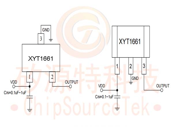
XYT1661 Pin Configuration:

XYT1661 Application Circuit:
.jpg)
XYT1661 Ordering Information:
|
Part Number
|
Package Type
|
Packing Qty
|
BOP (Gauss)
|
BRP(Gauss)
|
Temperature
|
Eco Plan
|
Lead
|
|
XYT1661WAD |
SOT23-3L |
3000pcs/Reel |
±30(Typ.) |
±20(Typ.) |
-40~ +85℃ |
ROHS |
Cu |
|
XYT1661MD |
SIP-3L |
1000pcs/Bag |
±30(Typ.) |
±20(Typ.) |
-40~ +85℃ |
ROHS |
Cu |
XYT1661 Block Diagram:


