Using a buck boost converter as a voltage regulator
Time:2023-05-01
Views:1053
Most applications or sub circuits require constant voltage power supply within a certain voltage tolerance range to ensure normal operation. Battery driven applications such as wireless sensors and personal handheld devices require voltage conversion to generate the required output voltage when the battery is discharged and the voltage drops accordingly. If the available power rails are not suitable for the required input voltage, or if the voltage change exceeds the required tolerance range, applications powered by fixed power rails (such as optical modules, wired sensors, active cables, or dongles) may also require voltage conversion.


This article explores whether the buck boost converter can become an ideal solution for voltage conversion and whether it can become a universal tool for any type of DC/DC voltage conversion.
When to use a buck boost converter
Generally speaking, if the available power supply voltage of a circuit or subcircuit is lower than the required voltage, the boost converter can effectively convert the DC voltage to a higher voltage level. If the available power supply voltage is higher than the required voltage, the buck converter will perform voltage conversion.
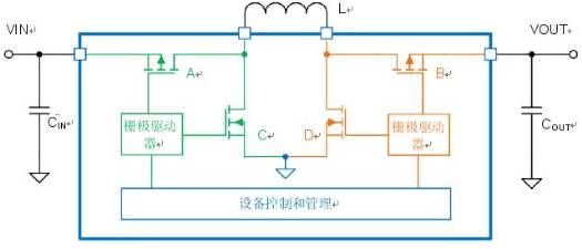
The buck boost converter is suitable for applications where the power supply voltage range is above and below the required output voltage. The buck boost converter consists of a buck converter and a boost converter, and the block diagram shown in Figure 1 more clearly reflects its structure.

Figure 1: Block diagram of buck boost converter
The buck boost converter combines the buck converter (green part in Figure 1) with the boost converter (orange part in Figure 1) in the same structure, effectively increasing and decreasing the output voltage. The control loop can determine whether the device needs to operate in step-down or step-up mode based on the actual input voltage and the programmed output voltage.
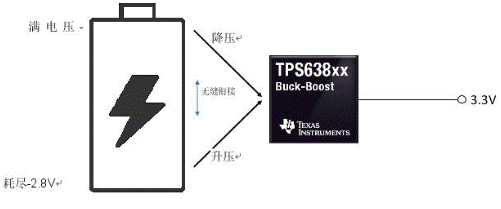
For example, suppose that a lithium ion battery with a typical voltage range of 4.2V to 2.8V is required to provide an output voltage of 3.3V. If a step-down converter is used, then the cutoff voltage of the battery must be greater than 3.3V. The disadvantage is that the power stored in the battery cannot be effectively used. The buck boost converter helps to fully utilize all the electrical energy of the battery, because when the input voltage is equal to or less than 3.3V, the buck boost converter can also consume the stored electrical energy, as shown in Figure 2.

Figure 2: The buck boost converter can completely deplete the battery‘s electrical energy
Using a buck boost converter as a voltage regulator
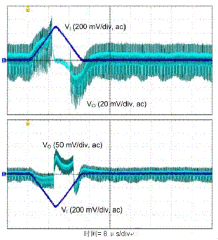
The second common use of buck boost converters is as voltage regulators. If there is a change in the power rail (such as 3.3V ± 10% change), and the load needs to adjust the voltage more (such as 3.3V ± 5% tolerance), then a step-down to step-up converter that can stabilize the voltage is needed. If the component is sensitive to power supply voltage (such as a cross resistance amplifier in an optical module); If other DC/DC pre regulators are not tightly regulated in industrial applications; Alternatively, if other components in the power path (such as fuses, load switches, or long cables) change voltage as the current increases, it may be necessary to adjust the voltage more strictly. Only using a boost converter or a buck converter cannot solve this problem. However, the buck boost converter can adjust the constantly changing input voltage to the required stricter limits. Figure 3 shows the transient response of TPS63802 to a fast ± 0.5 V/10 s line, with a significantly lower output voltage overshoot/overshoot than ± 0.1V.

Figure 3: TPS63802 at VI=VO=3.3V, Δ Transient response of the line at VI=± 0.5V
Other applications of buck boost converters
There are other reasons to choose a buck boost converter instead of simply choosing a buck boost converter. One reason is power ORing. Imagine a device like a baby monitor, powered by a 5V USB wall adapter or two AA main batteries, with a voltage range of 3V (when the battery is brand new) to 1.6V (when the battery is depleted). Only the buck boost converter can withstand a wide input voltage range from 5V (wall adapter) to 1.6V (wall adapter not connected and battery depleted), and still generate a 3.3V power rail for the system. In addition to the buck boost converter, you only need two external diodes to avoid cross current flowing from the wall adapter to the battery and seamlessly switch to the battery when pulling out the wall adapter.
Limitations of buck boost converter
When the input voltage approaches the output voltage, the internal control loop of the buck boost converter is usually designed to continuously switch between buck and boost modes. This operation method is acceptable, but it still has some drawbacks: mode switching may generate different switching frequencies, higher output voltage ripple, and more electromagnetic interference (EMI). The second negative impact is that the efficiency may slightly decrease at this time.
To avoid the negative impact of mode switching, it is possible to find devices with dedicated step-down and step-up modes that can maintain low levels of output voltage ripple. For example, TI‘s newly launched TPS638xx series buck boost converter has a buck boost mode and hysteresis characteristics that can avoid switching between easily filtered noise spectra and lower EMI.
Can step-down and step-up devices handle all types of voltage conversion?
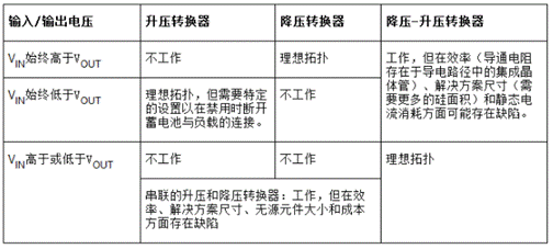
Due to the fact that the buck boost converter "includes" a buck converter and a boost converter, it can be used for DC/DC voltage conversion. So from this perspective, the answer is yes. But more details still need to be considered. Table 1 illustrates the given input voltage range and the required output voltage, as well as whether buck converters, boost converters, or buck boost converters can be excellent solutions.

Table 1: Overview of DC/DC conversion topology
Let‘s return to the initial question: Is there a universal tool for achieving DC/DC voltage conversion? Actually, it‘s not certain. When buck boost converters are not needed, simulation designers dedicated to high-capacity product development will prefer performance optimization of dedicated boost or buck converters. However, designers dedicated to the development of small volume products may believe that certain trade-offs are worth considering.
The use of buck boost conversion (to buck boost, buck boost, and boost) can bring the following benefits:
·Cross project expansion not only saves time, but also reduces design risks.
The number of different DC/DC converters can be reduced to a list of easy-to-use buck boost converters.
It can simplify the procurement process, reduce inventory complexity, improve price leverage and supply stability.
·Step-down boost can disconnect the load from the power supply during shutdown, while other topologies may require additional load switches.
|
Disclaimer: This article is transferred from other platforms and does not represent the views and positions of this site. If there is any infringement or objection, please contact us to delete it. thank you! |


