Service Hotline: 13823761625

Support

Contact Us

You are here:Home >> Support >> Technology

Technology

How EMI interferes with circuits through media

Time:2022-08-04 Views:1921
    Electromagnetic interference (EMI) is a part of our life. With the passage of time, a large number of intentional and unintentional EMI radiation sources will cause serious damage to the circuit. The signals of these radiation sources do not necessarily pollute the circuit, but our goal is to keep the low-noise system away from these hazards.

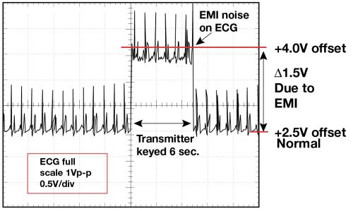
    We can imagine that a doctor wants to diagnose the heart accurately by using an ECG diagnostic device. Knowing that this is a high-precision measuring equipment, we will not worry about the annoying noise in the diagnostic results. This is a low-frequency measurement, and the electronic equipment will not exceed 1MHz. However, if an ECG device with poor EMI design is used, and the doctor uses his mobile phone to answer the phone during the examination, there is reason to worry about the diagnostic results. See Figure 1.
Figure 1 cardiac examination results of ECG diagnostic equipment when the transmitter beyond 1.5 feet (F = 470 MHz, p= 0.5W) is turned on and off

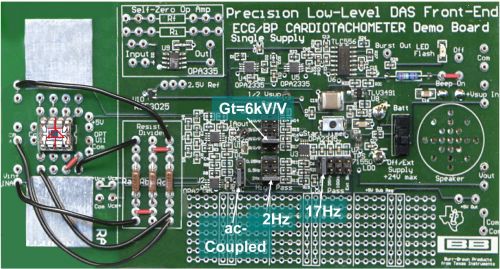
    In Figure 1, the cardiac input signal of the system is about 0.25 mvp-p. This small signal requires a measurement amplifier gain of about 6000 V / v. Fortunately, the situation shown in Figure 1 does not represent the actual performance of medical ECG measuring equipment. This measurement is actually carried out in the engineer‘s laboratory using the circuit board shown in Figure 2.
Figure 2 front view of circuit board of precision low-level ECG heart rate meter

    Don‘t fall into this EMI trap. Carefully build the circuit board and use some anti EMI components, which are independent of the bandwidth of analog or digital circuits. When there is an EMI source near the application circuit, the radiation source may or may not affect it.
    When using this low-frequency circuit board, how does the radiated noise from the mobile phone enter the measurement results (see Figure 1)? Let‘s review and study the whole EMI diagram. In terms of EMI, there are three factors at work: the radiation source, the coupling path of radiation signal transmission, and the radiation receptor.
    The radiation source in this example is obvious. However, the EMI signal source may be transmitted wirelessly through the air or through PCB, and the radiation source is unknown.
EMI (also known as radio frequency interference, RFI) forms a potential to surround the receptor through direct conduction or various field propagation. These fields are directly coupled into circuit connecting lines and PCB lines and converted into conductive RFI.
    Forming a force between two charges requires three conditions: electricity, magnetism, and electromagnetic field (radiation). The electric field (volts / distance) describes the force formed by the uneven charge distribution between two physical points. In order to balance this charge distribution, a force is formed between the charges.
    A moving charge or current forms a magnetic field, which exerts a force on all other charges around it. This field (or force) decreases rapidly with distance. Please note that the electric field and magnetic field are interrelated. One changes, and the other changes at the same time.
    Finally, the acceleration of electrons (or charges) forms an electromagnetic field. This electromagnetic field is the most common cause of EMI propagation.


    Disclaimer: This article is transferred from other platforms and does not represent the views and positions of this site. If there is infringement or objection, please contact us to delete. thank you!
    BD手机网页版官方登录入口-半岛彩票官方网站 ChipSourceTek

Baidu
map